
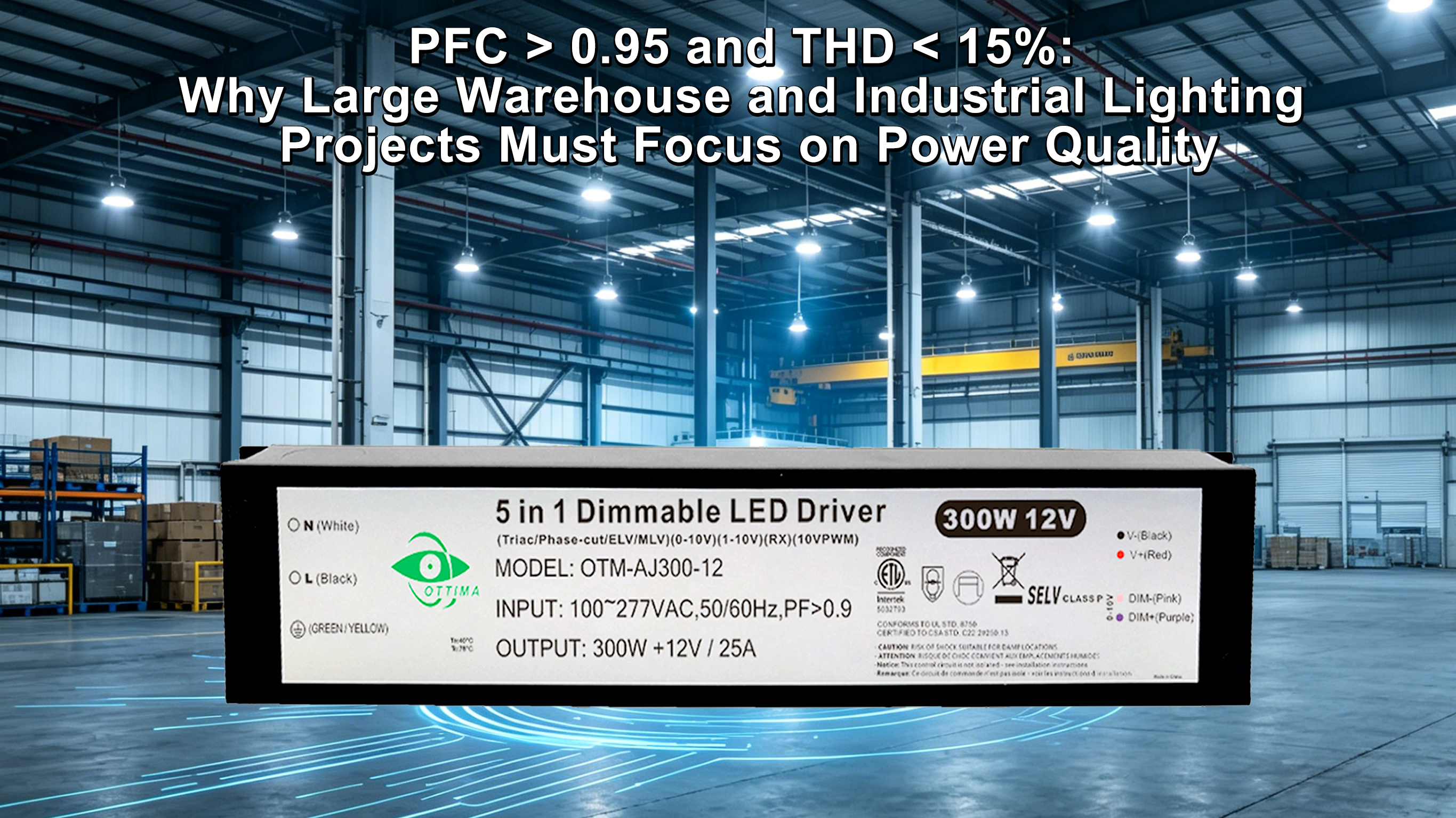
PFC > 0.95 and THD < 15%: Why Large Warehouse and Industrial Lighting Projects Must Focus on Power Quality
For electrical engineers and facilities managers overseeing large-scale industrial sites such as warehouses, manufacturing plants, or logistics parks, selecting an LED lighting system is never a one-time procurement task. When making decisions for hundreds or even thousands of high-power LED fixtures, seemingly minor differences in driver parameters can accumulate into massive operational costs and unpredictable system risks over the next five years.
Two parameters in the LED driver specification sheet are often overlooked, yet they directly determine your electricity bill, grid stability, and even whether you receive a "fine" from the power utility: Power Factor Correction (PFC) and Total Harmonic Distortion (THD).
This article provides an in-depth analysis of why, in large industrial lighting projects, insisting on drivers with PFC > 0.95 and THD < 15% is the only way to achieve the lowest Total Cost of Ownership (TCO) and the highest system reliability.
I. Power Factor (PFC): The "Invisible Thief" in Your Utility Bill and Capacity Killer
1.1 What is Power Factor (PFC)?
Power Factor (PFC) is an indicator measuring the efficiency with which electrical equipment utilizes electrical energy, with a value between 0 and 1.
Imagine the electrical energy supplied by the utility company as "Apparent Power" (unit: kVA), which consists of two parts:
1. Active Power (kW): The power that is genuinely converted into light, heat, or mechanical work, providing actual value (the power you want to pay for).
2. Reactive Power (kVar): The "extra" power needed to establish electromagnetic fields and maintain equipment operation (it performs no useful work but occupies grid capacity).
PFC = Active Power (kW) ÷ Apparent Power (kVA)
The closer the PFC is to 1 (the ideal value), the more efficiently the driver draws power from the grid, and the less reactive power it consumes.
1.2 The Hidden Cost of Low PFC: Utility Penalties and Increased Initial Investment
In large-scale industrial lighting scenarios, low-PFC drivers lead to two major economic and engineering problems:
A. Utility "Reactive Power Fines" (Exploding Operational Costs)
Most national and regional power utilities mandate that the average Power Factor for large industrial consumers must be maintained above 0.9 (the exact value may vary by region and voltage level).
Penalty Mechanism: If your lighting system causes the overall PFC to remain below this threshold for an extended period, the utility will charge you an additional "Reactive Power Fine" based on the amount of Reactive Power (kVar) consumed. This is not a one-time expense but a continuous monthly operating cost.
Compensation Measures: To avoid fines, facilities must install expensive Reactive Compensation Equipment (such as capacitor banks), which itself represents a significant initial investment and maintenance expense. Sourcing high-PFC drivers avoids these costs from the outset.
B. Transformer and Distribution Capacity Waste (Wasted Initial Investment)
When you use thousands of low-PFC (e.g., 0.85) drivers, the grid must supply significantly more Apparent Power than what is actually required.
Capacity Waste: Low PFC means your transformers, main switches, and cables must be sized according to the higher Apparent Power (kVA), even though your actual lighting load (kW) is low. This forces you to pay unnecessary costs for unused "reactive" capacity.
Procurement Goal: Insist on drivers with PFC > 0.95. A driver with PFC=0.98, compared to one with PFC=0.90, can save approximately 8% in apparent power capacity, directly lowering the specification requirements for transformers and distribution systems.
II. Total Harmonic Distortion (THD): "Noise Pollution" in the Grid and Safety Hazards
2.1 What is Total Harmonic Distortion (THD)?
Total Harmonic Distortion (THD) measures the degree of "waveform distortion" caused by the driver to the input current waveform during operation.
The ideal grid current should be a smooth sine wave. However, the switching nature of power supplies (including LED drivers) draws instantaneous current, which creates irregular "spikes" or harmonics in the current waveform. THD measures the intensity of these non-sinusoidal waves (harmonics).
THD = RMS value of all harmonics ÷ RMS value of the fundamental × 100%
The lower the THD, the closer the current waveform is to a pure sine wave, and the less pollution is caused to the grid.
2.2 In-Depth Analysis: Systemic Risks of High THD and Triple Harmonics
High THD is a more critical and hazardous issue faced by facilities managers.
A. Neutral Line Overheating Caused by Triple Harmonics
This is the most dangerous effect of high THD. In a three-phase, four-wire distribution system, odd, non-triple harmonics (like 5th, 7th) tend to cancel out in the neutral line. However, the currents of Triple Harmonics (3rd, 9th, 15th, etc.) have the same phase angle and directly add up on the neutral line.
Hazardous Consequences: If the driver's THD is too high, the accumulation of triple harmonics can cause the neutral line current to increase sharply, potentially exceeding the phase current. This leads to severe overheating of the neutral cable, accelerated insulation aging, and is a major hidden cause of electrical fires in industrial and commercial buildings.
B. Interference with Sensitive Equipment and Transformer Derating
High harmonic currents directly impact the reliability of equipment within the industrial park:
Precision Equipment Failure: Many sensitive devices in an industrial park (PLCs, VFDs, sensors, industrial robots) are highly sensitive to power quality. High harmonic distortion can interfere with the electronic components of these devices, leading to data errors, control system misjudgments, operational failures, and thus costly downtime.
Transformer Derating: Harmonic currents increase the iron and copper losses of transformers and distribution cabinets, leading to higher operating temperatures. To prevent thermal damage, facilities managers must derate the transformers, meaning the purchased transformer cannot be run at full capacity, representing another significant hidden cost.
Procurement Goal: Insist on drivers with THD < 15%. For facilities with extensive precision electronic equipment, strongly recommend high-end drivers with THD < 10%.
III. The Strong Link Between High Power Quality and Driver Lifespan
Beyond external grid risks, a low-power-quality driver itself implies a shorter lifespan and higher maintenance costs.
3.1 Poor PFC/THD and Internal Heat Generation
To achieve low-cost, low-PFC/high-THD, drivers often employ Passive PFC or simplified power topologies.
Heat Waste: This design typically results in lower driver efficiency. As discussed, inefficient drivers waste more energy as heat.
Lifespan Killer: This excess heat continuously acts upon the driver's most vulnerable component—the electrolytic capacitor. Capacitors are the life-determining factor of a driver, and their lifespan halves for every 10°C rise in temperature (the 10-Degree Rule).
3.2 TCO Analysis: Maintenance Costs Far Exceed Procurement Costs
In large projects, if drivers begin to fail in batches in the third year due to overheating or harmonic stress, the replacement and labor costs will be enormous:
Single Failure Cost: Driver cost + technician troubleshooting time + aerial lift/scissor lift rental + loss from production/operation downtime.
Long-Term Impact: Frequent failures not only affect production efficiency but also damage the company's reputation and client satisfaction.
Investing in drivers that use Active PFC, boast high efficiency (>93%), and low THD (<10%) is using a small procurement premium to hedge against years of potential massive maintenance and operational risks.
IV. ROI Analysis of High Power Quality
The cost of investing in high-PFC and low-THD drivers is usually only 5% to 15% higher than that of lower-quality drivers. However, in large industrial projects, the Return on Investment (ROI) period is extremely short, often recouping the cost within 1 to 2 years through savings in electricity and maintenance.
Evaluation Metric | Low-Quality Driver (PFC≈0.9, THD≈25%) | High-Quality Driver (PFC>0.95, THD<15%) | Value/Return |
Grid Efficiency | Low (High Reactive Power) | High (Near 1) | Saves reactive power fines and energy loss |
Neutral Line Current | Hazardous (Triple Harmonics add up) | Safe (Good Harmonic Suppression) | Avoids fire and cable replacement costs |
Sensitive Equipment Interference | High (Causes system failure) | Low (Pure Waveform) | Extends precision equipment lifespan, reduces maintenance costs |
Transformer Requirements | Requires extra capacity or derating | Can run at full capacity | Reduces initial transformer investment |
Initial Investment | Slightly Lower | Slightly Higher | Quality premium recouped in 1-2 years via electricity/maintenance savings |
V. Professional Procurement Advice: How to Ensure the True Quality of the Driver
As a professional B2B buyer, you must use expert standards to verify supplier commitments:
1. Distinguish Active vs. Passive PFC:
Active PFC: Uses a dedicated IC control circuit, resulting in high efficiency, easily achieving PFC above 0.95, and THD typically controlled below 10%. This is the standard for industrial lighting.
Passive PFC: Relies on passive components like capacitors and inductors, lower cost, but PFC is usually capped around 0.9, and THD tends to be higher.
2. Verify Third-Party Test Reports: Do not trust the label on the spec sheet alone. Demand detailed test reports issued by a reputable third-party authority (such as TUV, DEKRA) to confirm the actual measured values of PFC and THD.
Confirm Load Conditions: The THD value changes with the load. Ensure you test or request reports for THD at near-full load (>90%), as this is the most common operating state in real-world applications.
International Standard Compliance: Prioritize drivers that comply with the International Electrotechnical Commission (IEC) standard IEC 61000-3-2 (Class D) harmonic current limits. This is the fundamental threshold to ensure the driver does not pollute the grid.
Choosing a high-performance driver is purchasing "power insurance" for the long-term stable operation of your project, and it is the cornerstone of the optimal Total Cost of Ownership solution.
Are you planning a large industrial or warehouse lighting project?
We provide customized driver and system optimization services, capable of precisely matching driver solutions that meet PFC > 0.95 and THD < 15% based on your grid environment and equipment type. Contact our engineering experts for a free "Power Quality" risk assessment and product recommendation.


