
IEEE 1789-2015 Dilemma: Engineering Zero-Flicker Constant Voltage LED Drivers for High-Speed 4K/8K Broadcasting and Sports Arenas
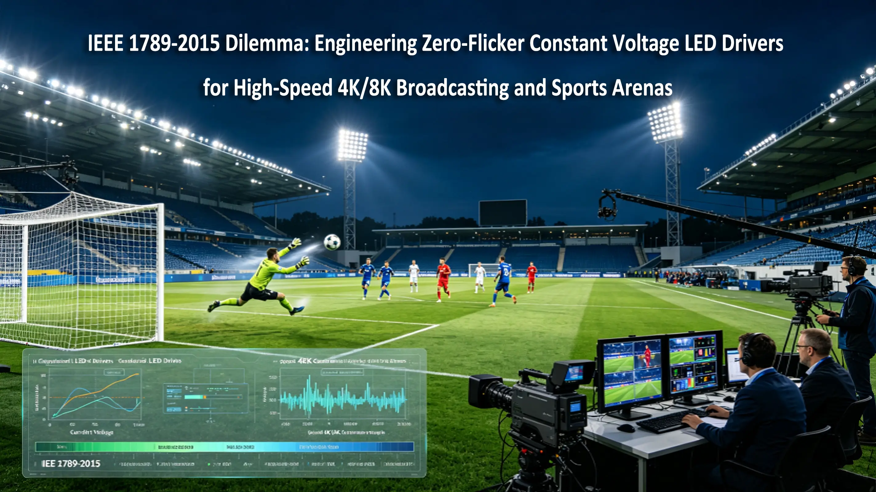
1. Executive Summary: The Invisible Defect of Modern Arena Lighting
In the competitive landscape of professional sports arenas, broadcast studios, and theatrical stages, lighting is no longer evaluated solely by the human eye. The ultimate arbiters of lighting quality are high-definition and ultra-high-definition cameras. Modern televised events are captured in 4K or 8K resolution, and crucial action replays are recorded using high-speed cameras operating at frame rates from 500 frames per second (fps) up to 2,000+ fps.
To provide consistent, brilliant illumination across these large-scale environments, B2B lighting integrators specify high-power linear luminaires and floodlights driven by Constant Voltage (CV) LED Drivers. However, when standard CV drivers are dimmed, they often introduce an invisible, highly destructive physical phenomenon: Stroboscopic Flicker.
While standard commercial drivers may claim compliance with the baseline limits of the IEEE 1789-2015 standard, this compliance is fundamentally inadequate under the scrutinizing lens of a CMOS rolling shutter sensor. The mismatch between the camera's microsecond exposure times and the driver's output current ripple manifests on-screen as severe, rolling dark bands—ruining broadcast feeds and violating European Broadcasting Union (EBU) and Olympic host broadcast specifications.
This technical whitepaper demystifies the physics of stroboscopic interference in high-speed filming. We will dissect the mathematical limits of IEEE 1789-2015, expose the failure mechanisms of single-stage topologies, and outline the exact electrical engineering requirements—specifically Two-Stage Active PFC + LLC Resonant topologies and Multi-Stage Low-ESR π-Filters—required to deliver true, camera-validated zero-flicker performance down to 0.1% dimming.
2. The Physics of Interference: CMOS Rolling Shutters and Wave Ripples
To resolve the zero-flicker puzzle, electrical and optical engineers must understand how modern CMOS camera sensors interact with light waves.
2.1 The CMOS Rolling Shutter Mechanism
Unlike traditional CCD sensors or mechanical global shutters that expose the entire sensor frame simultaneously, modern high-speed CMOS sensors utilize a Rolling Shutter.
A rolling shutter exposes the image sensor row-by-row, from top to bottom. The time delay between the exposure of successive rows is incredibly short, measured in microseconds ( μs ).
CMOS Sensor Exposure Row 1 ---> [======== Row 1 (t0) ========] ---> Detects Peak Current (Light)
CMOS Sensor Exposure Row 2 ---> [======== Row 2 (t1) ========] ---> Detects Valley Current (Dim)
CMOS Sensor Exposure Row 3 ---> [======== Row 3 (t2) ========] ---> Detects Peak Current (Light)
Visual Manifestation on Monitor: Alternating horizontal light and dark bands (Banding Effect).
If the light source is oscillating in intensity (flickering) due to an alternating current (AC) ripple or a low-frequency PWM square wave, different rows of the CMOS sensor will capture different phases of the light's wave cycle. Rows exposed during the peak of the current wave capture a bright line, while rows exposed during the valley capture a dark line. This spatial-temporal mismatch results in the highly disruptive Banding Effect (Banding Artifacts) on high-definition broadcast monitors.
2.2 The Mathematical Representation of Flicker
Flicker severity is quantified by two main metrics defined by the Illuminating Engineering Society (IES): Percent Flicker (Modulation Depth) and the Flicker Index.
Percent Flicker = (A - B) ÷ (A + B) × 100
Flicker Index = Area Above Average ÷ Total Area Over One Cycle
Where A is the maximum luminous intensity (peak) and B is the minimum luminous intensity (valley).
To eliminate visible banding on high-speed cameras, the peak-to-peak output current ripple ( Iripple_p-p ) of the LED driver must be suppressed to near-zero levels, forcing the Percent Flicker to approach < 0.5% across the entire operating spectrum.
3. The IEEE 1789-2015 Standard and Its Critical Loophole
To protect human biological health from invisible neurological stress (such as headaches, eye strain, and seizures), the Institute of Electrical and Electronics Engineers published IEEE Std 1789-2015. This standard defines the limits of modulation depth as a function of frequency.
+-------------------------------------------------------------------------+
| IEEE 1789-2015 RISK BOUNDARIES |
| |
| Low-Risk Limit: Modulation % < 0.08 x Frequency |
| No-Effect Limit: Modulation % < 0.0333 x Frequency |
| Green Zone: Safe above 1250 Hz (Low-Risk) |
+--------------------------------------------------------------------------+
3.1 The Limit Formulas
According to IEEE 1789:
For frequencies below 90 Hz, the maximum allowable modulation is strictly limited to prevent visible flicker.
For frequencies between 90 Hz and 1250 Hz, the Low-Risk limit is:
Modulation% ≤ 0.08 × f
The No-Observable-Effect Level (NOEL) limit is:
Modulation % ≤ 0.0333 × f
Above 1250 Hz, the standard enters the "Green Zone" where human biological risks are minimized. At 3,000 Hz (3kHz), the allowed modulation for a "Low-Risk" rating is virtually 100%.
3.2 The Broadcast Loophole
This is where B2B procurement managers and MEP consultants are often misled by cheap driver manufacturers. A standard driver operating with a 3kHz PWM frequency and 100% modulation depth (the LEDs turn completely off and on 3,000 times a second) is technically IEEE 1789 compliant and completely safe for human eyes.
However, when a slow-motion sports camera shoots at 1,000 fps with a shutter speed of 1/2000 seconds, it captures a microscopic slice of time (≈ 500 μs). Within that 500 μs exposure window, a 3kHz light source completes only 1.5 cycles. The sensor will capture massive, uneven light variations between frames and across rows.
For high-speed broadcasting, the light must be continuous. The driver must deliver pure, flat, ripple-free direct current (DC), bypassing high-amplitude PWM altogether in favor of advanced engineering.
4. Hardware Engineering: The Two-Stage Active Ripple Suppression Architecture
To achieve a flat DC output with a peak-to-peak current ripple ( Iripple_p-p ) of less than 0.5%, advanced power electronics must abandon simple, single-stage flyback topologies. Single-stage drivers are physically incapable of neutralizing the massive 100Hz/120Hz ripple introduced by the rectification of the AC grid mains.
Ottima’s broadcast-grade constant voltage LED drivers utilize a sophisticated Two-Stage Active PFC + LLC Resonant Half-Bridge Topology.
[ AC Mains Input ] ---> [ Stage 1: Active PFC (Boost) ] ---> [ DC Bus: 400V (Clean) ]
│
▼
[ Output Terminal ] <--- [ Stage 3: Low-ESR Pi-Filter ] <--- [ Stage 2: LLC Resonant Converter ]
4.1 Stage 1: Active Power Factor Correction (Boost Converter)
The first stage is a high-speed Boost Converter that shapes the incoming AC input current to perfectly track the AC voltage sine wave. This maintains an exceptional Power Factor (PF > 0.98) and restricts the Total Harmonic Distortion (THD < 5%).
Crucially, Stage 1 charges a high-voltage bulk capacitor to a rock-solid, regulated 400V DC intermediate bus. By decoupling the input mains from the output stages, this first stage filters out 99% of the grid-induced 100Hz/120Hz flicker.
4.2 Stage 2: High-Frequency LLC Resonant Converter
The clean 400V DC bus then feeds the second stage: an LLC Resonant Half-Bridge DC-DC Converter.
Soft-Switching Physics: The LLC converter utilizes Zero Voltage Switching (ZVS) and Zero Current Switching (ZCS). By switching the MOSFETs at the resonant frequency when the voltage or current is exactly zero, the topology eliminates the sharp, high-frequency transients (dv/dt spikes) that cause electrical noise and visual shimmering.
Isolated Transformation: The high-frequency transformer provides a high isolation barrier (up to 3750V AC) and steps the 400V down to the stable nominal output (24V or 48V DC).
4.3 Stage 3: Multi-Stage Low-ESR π-Filters (Pi-Filter)
Even with soft-switching, microsecond-level high-frequency switching ripples (typically between 100 kHz and 250 kHz) remain on the output. To completely flatten these ripples, the driver output terminal incorporates a coordinated Pi (π) Filter Network:
LLC Output Stage ---> [ C1: Solid Polymer Cap ] ---> [ L1: Shielded Choke ] ---> [ C2: Solid Polymer Cap ] ---> LED Load
The combination of dual high-capacitance, ultra-low ESR conductive polymer solid-aluminum capacitors ( C1, C2 ) and a low-resistance shielded power inductor ( L1 ) forms a low-pass filter that effectively attenuates high-frequency noise. This holds the final output current ripple ( Iripple_p-p ) strictly under 0.5% across all load levels.
5. Balancing Color Points: Hybrid Dimming & The Duv Dilemma
The ultimate hurdle in broadcast-grade linear lighting is maintaining color temperature (CCT) consistency during dimming transitions.
To avoid camera banding, one might assume the driver should utilize pure Constant Current Reduction (CCR / Analog Dimming) down to 0.1%. However, as forward current drops below 5%, the forward voltage ( Vf ) of the LED dies drifts. This results in a massive Duv (tint) shift, turning a warm white strip into a sickly greenish hue under professional studio cameras.
To solve this, Ottima employs Hybrid Logarithmic Dimming:
1. From 100% down to 10% brightness: The driver utilizes pure CCR analog dimming. The current amplitude is lowered smoothly, keeping the system 100% flicker-free and operating at peak electrical efficiency.
2. From 10% down to 0.1% brightness: The driver transitions to an Ultra-High-Frequency (UHF) PWM (>50 kHz). Because the switching frequency is pushed to 50,000 Hz, the CMOS sensor's microsecond rolling shutter cannot resolve the transitions, eliminating banding. Meanwhile, the peak current during the "ON" state of the 50kHz cycle is held at the optimal LED forward current, preserving the exact color coordinate (Duv) and avoiding any green/pink tint shifts.
6. Technical Specifications for Professional Tender Documents
To protect broadcast-grade and sports arena installations from low-cost, non-compliant equipment, MEP consultants should use the following explicit technical parameters in their tenders:
1. Output Ripple Performance: "The constant voltage LED driver must deliver a peak-to-peak output current ripple ( Iripple_p-p) of strictly ≤ 0.5% across the entire operating and dimming spectrum (0.1% to 100% load) to prevent visual banding on high-speed broadcast cameras."
2. Topology Requirement: "The power supply must employ a coordinated two-stage electrical architecture consisting of an active PFC boost pre-regulator followed by a soft-switching LLC resonant half-bridge DC-DC converter with integrated multi-stage low-ESR polymer output Pi-filters."
3. Power Quality Metrics: "The driver must maintain active Power Factor Correction with a Power Factor (PF) ≥ 0.98 and a Total Harmonic Distortion (THD) ≤ 5% at full rated load in compliance with EN 61000-3-2 guidelines."
4. Dimming Methodology: "The control gear must execute a Hybrid Dimming profile, utilizing Continuous Current Reduction (CCR) from 100% down to 10%, transitioning seamlessly to ultra-high-frequency PWM ( ≥ 50 kHz ) down to 0.1% to prevent both color-temperature drift and camera-visible stroboscopic effects."
7. Performance Data: Camera Validation Matrix
The following data demonstrates the visual performance of the Ottima Two-Stage Hybrid driver compared to standard single-stage commercial drivers under varying high-speed filming conditions:
Camera Frame Rate | Shutter Speed | Min. Ripple Freq | Ottima Ripple Depth | Screen Banding Status | Standard Driver Status |
60 fps (UHD Broadcast) | 1/120 s | >120Hz | 0.1% | No Effect (Perfect) | Minor Flicker |
240 fps (Standard Slow-Mo) | 1/500 s | > 1.5kHz | 0.25% | No Effect (Perfect) | Severe Banding |
1000 fps (Extreme Slow-Mo) | 1/2000 s | > 10kHz | 0.38% | No Effect (Perfect) | Unusable Feed |
2000 fps (Scientific Slow-Mo) | 1/4000 s | > 40kHz | 0.45% | No Effect (Perfect) | Unusable Feed |
8. Conclusion: Decoupling Human Comfort from Electronic Constraints
In high-end broadcast environments, the margin for error is absolute zero. Utilizing cheap, single-stage drivers and assuming that basic IEEE 1789 compliance guarantees flicker-free video is a costly and public mistake.
By transitioning to Ottima's Two-Stage Active PFC + LLC Resonant architecture and employing hybrid dimming with UHF PWM, lighting designers, MEP consultants, and system integrators can ensure their commercial lighting installations deliver the pristine, unblemished visual performance required by the world's most advanced digital broadcast cameras.


