20W 12V/24V IP20 Constant Voltage Lever Terminal Block
■ Features:
·Output constant Voltage
·Range: 85-265VAC
·Built-in active PFC function
·Efficiency up to 82%
·Protections: short circuit/over load /over temperature
·Cooling by free air convection
·IP20 design for indoor installation.
·Dimming function: Built in DALI interface dimming function conform
to DALI Protocol IEC62386
·Push dimming function
·Dimming range: 0-100%, LED start at 0.1% possible
·Suitable for intelligent LED lighting
■ Specification
Model | OTM-DD20-12 | OTM-DD20-24 |
Output | DC Voltage | 12V | 24V |
Voltage Tolerance | ±0.5V |
Voltage Regulation | ±0.5% |
Rated current | 1.66A | 0.83A |
Rated power | 20W |
Load Regulation | ±2% |
Input | Voltage Range | 85-265VAC |
Frequency Range | 47 - 63Hz |
Power Factor(Typ.)@ full load | PF≥0.96 / 120VAC PF≥0.9/ 230VAC (Full loading) |
THD(Typ.)@ full load | <20% |
Efficiency(Typ.)@ full load | 77% | 82% |
AC Current(Max.) | 0.22A |
Inrush Current (Typ.) | 1.48A/120VAC 16A/230VAC |
Leakage current | <0.5mA |
Protection | Short Circuit | constant current mode, recover automatically after fault condition is removed |
Over Load | ≤120% constant current limiting, recover automatically after fault condition is removed |
Over temperature | 100℃±10℃ |
Protection Class | II |
Environment | Working TEMP. | -40~+60℃ (see below derating curve) |
Working Humidity | 20 - 95%RH ,non-condensing |
Storage TEM.,Humidity | -40 - +80℃,10 - 95%RH |
TEMP.coefficient | ±0.03%/℃(0 - 50℃) |
Vibration | 10~500Hz, 2G 10min./1 cycle,period for 60min. each along X,Y,Z axes |
Safety & EMC | Safety standards | EN61347-1:2015 EN61347-2-13:2014 EN62493:2010 IP20 |
Withstand voltage | I/P-O/P:3.75KVAC |
Isolation resistance | I/P-O/P:100MΩ/500VDC/25℃/70%RH |
EMC Emission | EN55015 EN61000-3-2 EN61000-3-3 |
EMC Immunity | EN61000-4-2,3,4,5,6 ,11, EN61547 |
Others | Net Weight | 0.21KG |
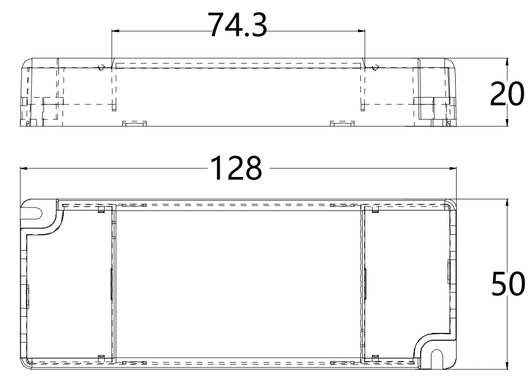
Dimension | 128*50*20mm (L*W*H) |
packing | 40*30*500px /100PCS/CTN |
Notes | 1. All parameters NOT specially mentioned are measured at 230VAC input , rated load and 25℃of ambient temperature. 2. Tolerance: includes set up tolerance, line regulation and load regulation . 3. The power supply is considered as a component that will be operated in combination with final Equipment. Since EMC performance will be affected by the complete installation, the final equipment manufactures must be-qualify EMC Directive on the complete installation again. |
■ Mechanical Specification
Input & Output wiring
※Input terminal with Live Wire(L) , Neutral Wire (N)
※Output LED SEC (LED+), output negative (LED). Connected to LED Lamps
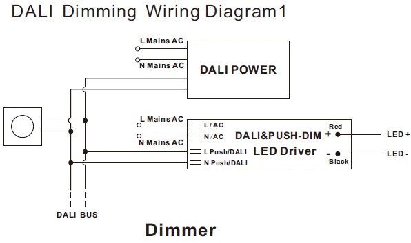
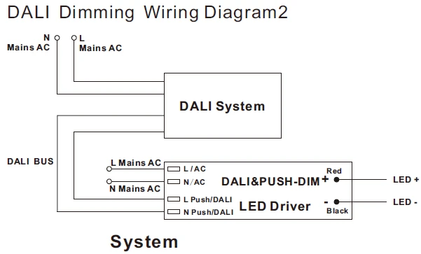
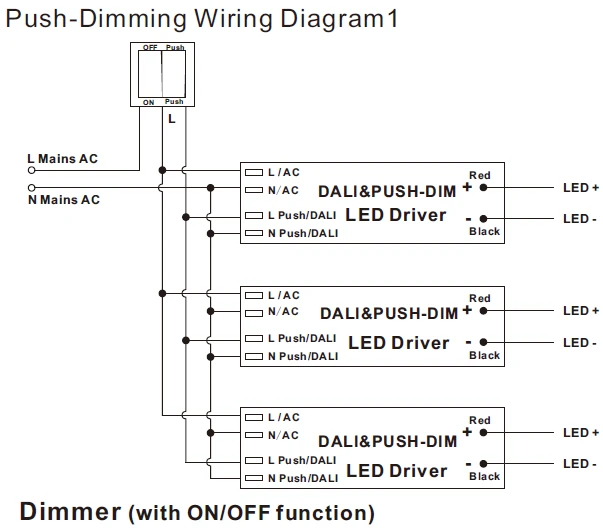
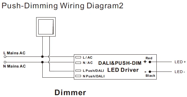
Dimming wiring
※Dimming wires are installed for Dimming terminals (No polar) and are connected to the DALI BUS when use DALI function .
wire (N) is connected to AC (N) while and wire (L) is connected to Push dim switch dimmer( L) when use Push function.
※Please make sure you connect these correctly otherwise your product will not function correctly and could be damaged.
※Note:
Any other requests we can customize.
Suggested wire diameter: primary: 0.5-2.5mm²; Secondary: 0.5-2.5mm²
■ Dimming Operation
----------------------------------------------------------------------------------------------------------------------------------------------------------------------------------------------------------------------------------------------------------------------------------
---------------------------------------------------------------------------------------------------------------------------------------------------------------------------------------------------------------------------------------------------------------------------------
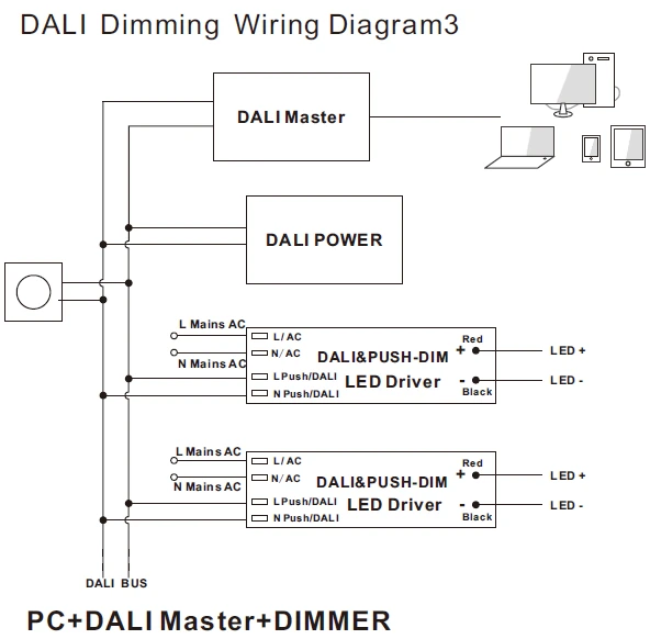
Note: For DALI Dimming Wiring Diagram 3, please noted that only one DALI power is need in the DALI bus, so no extra DALI power is needed if the Master or Dimmer already includes the DALI Power.
■ Derating Curve

※To extend their life, please refer to the Derating Curve and derate according to the temperature.
■ Instruction:
1)This driver should be installed by qualified and professional person;
2)Please make sure the driver is installed with adequate ventilation around it to allow for heat dissipation.
3)Ensure that wiring is correct before test in order to avoid light and power supply damage;
4)If driver Cannot work normally, don’t maintain privately; Have any question, please contact us.


