
Advanced 10kV/15kV Surge Protection Architectures in Outdoor Facade and Street Lighting Drivers
1. Executive Summary: The Hostile Canopy of Municipal Infrastructure
In the deployment of smart city infrastructure, street lighting and architectural facade illumination occupy the most physically and electrically vulnerable positions imaginable. Mounted atop 15-meter steel poles or affixed to the exposed apex of commercial skyscrapers, these luminaires act as literal lightning rods.
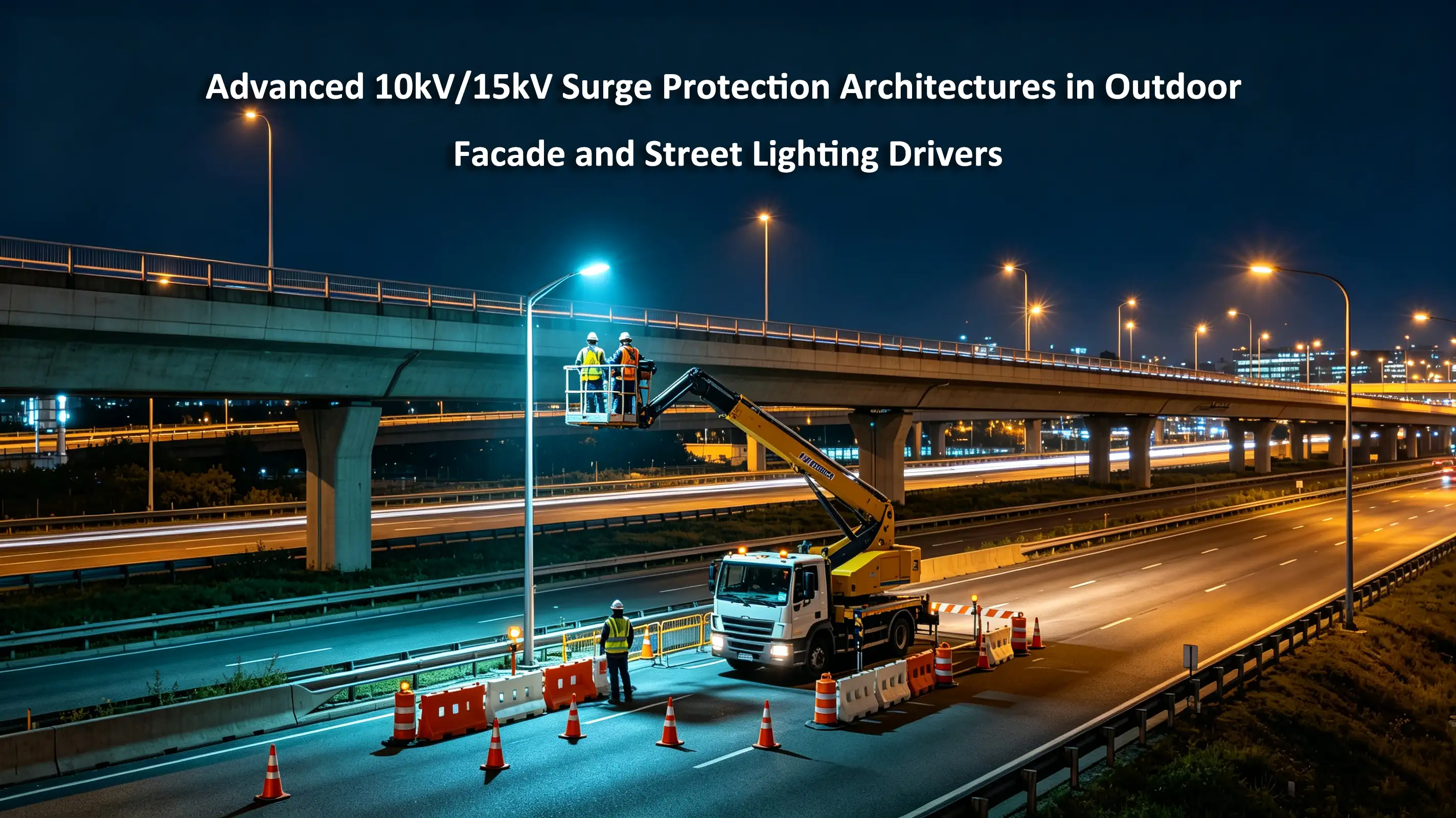
For municipal planners, Energy Service Companies (ESCOs), and Engineering, Procurement, and Construction (EPC) contractors, the failure of an outdoor LED driver due to a lightning strike or grid transient is not merely a technical glitch; it is an Operational Expenditure (OPEX) disaster. Replacing a blown driver on a highway overpass or a dynamic media facade requires highly paid electrical contractors, specialized bucket trucks, lane closures, and significant civic disruption.
While generic commercial LED drivers claim to offer "built-in surge protection," these claims usually refer to a single, inadequate Metal Oxide Varistor (MOV) that will violently explode under a direct Category C transient.
This advanced technical whitepaper deconstructs the absolute electrical engineering required to design and specify true 10kV/15kV outdoor LED drivers. We will dissect the IEEE C62.41.2 Combination Wave transient model, map the destructive pathways of Differential and Common Mode surges, and outline the precise electrical physics behind the Three-Stage GDT-MOV-TVS Coordination Circuit necessary to guarantee a zero-maintenance outdoor lighting network.
2. Decoding the Threat: The IEEE C62.41.2 Transient Model
To engineer a defense system, one must first quantify the weapon. In North America and international smart city projects, transient overvoltages in outdoor environments are defined by IEEE C62.41.2.
Street lighting and facade luminaires fall strictly under Category C (High Exposure - Outdoors). Lightning strikes, whether direct hits to the municipal grid or indirect inductive coupling, produce a violent burst of electromagnetic energy known as a Combination Wave.
The Anatomy of the Combination Wave (1.2/50μs Voltage & 8/20μs Current)
A Category C transient does not behave like normal electricity; it behaves like an explosive shockwave.
The Voltage Wave (1.2/50μs): The transient voltage spikes from zero to its peak (e.g., 10,000 Volts) in an incredibly fast 1.2 microseconds, before decaying to 50% of its peak value in 50 microseconds. This extreme rate of change ($dv/dt$) instantly overwhelms standard dielectric insulation, causing high-voltage arcing across PCB traces.
The Current Wave (8/20μs): The kinetic, destructive force of the strike is carried by the current. It surges to its peak (e.g., 5,000 Amperes or 5kA) in 8 microseconds and decays in 20 microseconds.
When a 10kV/5kA surge hits a standard LED driver, the energy injected into the circuit (E =ʃ v(t)i(t)dt) exceeds hundreds of Joules in milliseconds, vaporizing standard silicon components and blowing the physical casing apart.
3. Mapping the Attack Vectors: Differential vs. Common Mode
Transients infiltrate the LED luminaire through two distinct electrical pathways. A robust driver architecture must independently block both.
3.1 Differential Mode Surges (Line-to-Line / Line-to-Neutral)
The Pathway: The transient travels directly between the active power conductors (Live and Neutral).
The Source: Typically caused by localized grid anomalies, such as a municipal substation switching massive capacitor banks, or a localized lightning strike on the primary distribution line.
The Destruction: A Differential Mode surge rides the normal power path. It smashes directly into the driver’s input EMI filter, destroys the Bridge Rectifier, and annihilates the primary switching MOSFETs. Because the energy is trapped within the primary circuit, it usually blows the internal fuse, permanently killing the driver.
3.2 Common Mode Surges (Line-to-Ground / Neutral-to-Ground)
The Pathway: The transient travels between the power conductors (L or N) and the Earth Ground (the metal chassis of the luminaire).
The Source: This is the primary signature of an indirect lightning strike or a direct hit to the steel light pole. The massive electromagnetic field of the lightning induces a voltage spike uniformly across all power lines simultaneously, seeking the shortest path to earth.
The Destruction: Common Mode surges are highly insidious. Because the voltage rises on both Live and Neutral simultaneously, the bridge rectifier might survive. Instead, the 10kV surge looks for a path to the grounded metal chassis. It will jump across the galvanic isolation barrier (the main transformer), arcing directly into the secondary low-voltage DC side. It instantly incinerates the sensitive LED chips and often welds the LED circuit board to the aluminum heatsink.
4. The Arsenal: Evaluating Suppression Components
To arrest a 10kV/5kA combination wave, engineers must utilize specific suppression components, each with unique physical characteristics, advantages, and fatal flaws.
1. Metal Oxide Varistor (MOV): A voltage-dependent resistor. Under normal 277V AC, it acts as an insulator. When a surge hits, its resistance drops exponentially in nanoseconds, clamping the voltage and shunting the current.
The Flaw: MOVs are sacrificial. Every surge they absorb degrades their crystalline structure, lowering their clamping voltage. Eventually, they leak current, overheat, and catch fire.
2. Gas Discharge Tube (GDT): A ceramic tube filled with inert gas. Under massive overvoltage, the gas ionizes into a plasma, creating a near-perfect short circuit to earth. It can handle massive currents (10kA+) without degrading.
The Flaw: GDTs are "slow." They take microseconds to ionize, during which the lethal voltage spike passes straight through to the electronics. Furthermore, they have a high "let-through" voltage.
3. Transient Voltage Suppressor (TVS) Diode: A semiconductor device designed for avalanche breakdown. It responds in picoseconds and clamps the voltage with incredible precision.
The Flaw: TVS diodes have very low energy capacity. A direct 5kA lightning surge will vaporize a TVS diode instantly.
5. The Ultimate Defense: The Three-Stage Coordination Circuit
Because no single component can provide both the massive energy absorption required and the nanosecond response time needed, Ottima’s outdoor municipal LED drivers employ a Three-Stage Coordinated Surge Architecture.
[ AC Grid Input L/N ]
│
▼
[ STAGE 1: Gas Discharge Tube (GDT) - Common Mode Heavy Lifter ]
│ └─ Shunts 10kA massive current directly to Earth Ground.
▼
[ DECOUPLING INDUCTOR NETWORK ]
│ └─ Creates a physical delay (v = L frac{di}{dt}$), forcing the fast surge backwards.
▼
[ STAGE 2: Thermally Protected MOV (TMOV) - Differential Clamping ]
│ └─ Reacts in nanoseconds, clamping the 10kV spike down to ~1.5kV.
▼
[ STAGE 3: Transient Voltage Suppressor (TVS) - Precision Sniper ]
│ └─ Absorbs the residual ripple, clamping precisely to the semiconductor safe limit.
▼
[ Safe 277V AC to Rectifier & PFC Stage ]
The Physics of Coordination (Why the Inductor matters)
If you place a fast MOV and a slow GDT in parallel without an inductor between them, the fast MOV will trigger first, absorb all the kinetic energy, and explode before the GDT even realizes a surge is happening.
Ottima places precise Decoupling Inductors between Stage 1 and Stage 2. Because an inductor violently opposes rapid changes in current ( v = L di/dt ), when the 1.2 μs lightning strike hits, the inductor acts as a temporary brick wall. This forces the voltage to back up and rise instantaneously across the GDT, triggering the gas plasma ionization. The GDT safely shunts 95% of the lightning energy to ground, leaving the MOV and TVS to easily clean up the residual noise.
This coordination guarantees that the driver survives thousands of lightning events over a 10-year lifespan without component degradation.
6. B2B Economic Evaluation: The TCO of Municipal Street Lighting
For municipal CFOs and ESCO project managers, the initial Capital Expenditure (CAPEX) of procuring premium outdoor LED drivers with 10kV/15kV three-stage protection represents an insignificant premium of perhaps $15 to $20 per luminaire over standard 4kV commercial drivers.
However, the Total Cost of Ownership (TCO) calculation heavily favors premium engineering:
The Cost of Failure: If a severe thunderstorm rolls through a city and destroys 300 streetlights equipped with generic drivers, the municipality faces a devastating OPEX bill.
The Truck Roll: Dispatching a two-man union electrical crew with a bucket truck costs an average of $300 to $500 per fixture replaced. A single storm can inflict a $150,000 maintenance liability.
Investing in Ottima’s highly coordinated surge architectures is an insurance policy with a guaranteed payout. It effectively zeroes out weather-related maintenance budgets, allowing ESCOs to secure long-term performance contracts without fear of catastrophic OPEX erosion.
7. Technical Specifications for Public Tenders
To shield municipal and architectural facade projects from substandard control gear, MEPs and civic engineers must copy and paste the following parameters into their public tender documents:
1. Category C High Exposure Compliance: "All outdoor LED drivers must be independently tested to withstand a minimum of 10kV / 5kA combination wave transients in accordance with IEEE C62.41.2 Category C High requirements."
2. Surge Coordination Architecture: "The LED power supply must employ a coordinated, multi-stage transient suppression topology utilizing Gas Discharge Tubes (GDT), decoupling inductors, and Metal Oxide Varistors (MOV). Single-component MOV protection is strictly prohibited."
3. Common and Differential Mode Immunity: "Surge suppression circuitry must provide distinct, absolute protection pathways for both Differential Mode (L-to-N) and Common Mode (L-to-G, N-to-G) transients to prevent dielectric breakdown across the galvanic isolation barrier."
8. Conclusion: Engineering for the Unpredictable
The outdoor environment is fundamentally unpredictable. A city's lighting grid must be engineered not just to illuminate, but to survive.
By demanding IEEE C62.41.2 compliance, understanding the distinct threats of Common vs. Differential mode strikes, and deploying drivers equipped with GDT-MOV-TVS coordinated circuits, B2B stakeholders can construct municipal lighting networks that are as resilient as they are efficient. In the realm of smart cities and architectural facades, superior surge protection is the invisible bedrock of operational success.


