
Eliminating Ground Loops and Signal Offset in Massively Paralleled 0-10V Commercial Lighting Networks
Introduction: The Scale Paradox in Commercial Lighting Control
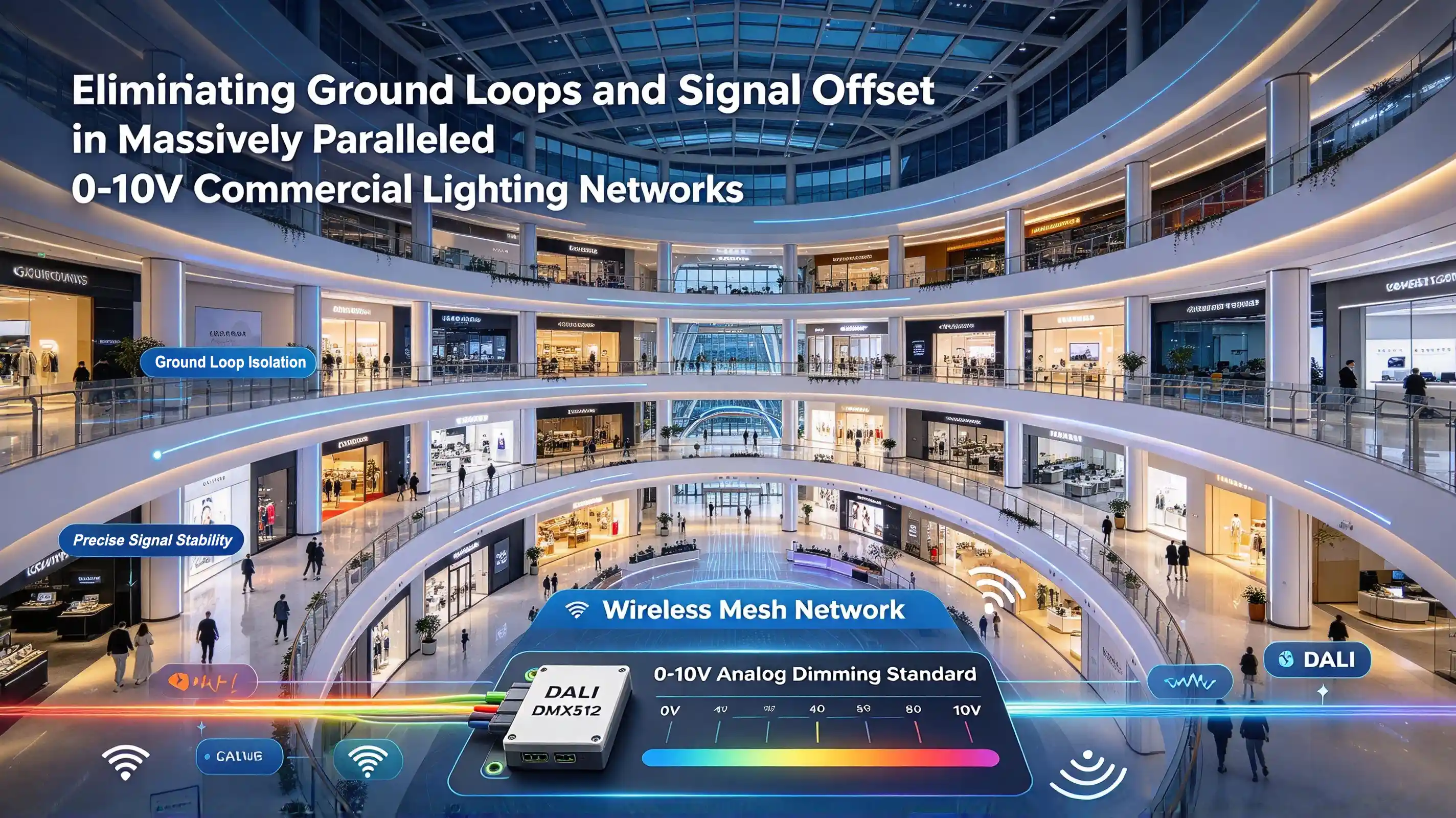
Modern commercial real estate—spanning sprawling multi-story shopping complexes, expansive logistics centers, corporate office towers, and high-end retail supermarkets—demands lighting control architectures capable of managing thousands of fixtures simultaneously. Despite the rapid ascent of digital protocols like DALI, DMX512, and wireless mesh networks, the analog 0-10V dimming standard remains an industry workhorse. Its structural simplicity, cost-effectiveness, and universal compatibility across disparate LED driver ecosystems ensure its continued prevalence in large-scale commercial retrofits and new builds.
However, as electrical and lighting engineers scale up 0-10V topologies, connecting dozens or even hundreds of LED drivers in parallel across a single central lighting controller or building management system (BMS), a persistent and insidious set of performance failures frequently emerges. Installers and maintenance engineers routinely report baffling anomalies:
LED fixtures refusing to turn completely off, lingering stubbornly at a residual 10% brightness floor even when the controller outputs 0V.
Entire rows or zones of luminaires exhibiting low-frequency, synchronized "breathing" or pulsing flicker.
Erratic dimming response curves where fixtures across different electrical sub-panels track disparate light output levels despite receiving identical control voltage commands.
At the heart of these widespread field failures lies a fundamental electro-mechanical phenomenon: Ground Loops and Signal Offset Accumulation caused by non-isolated interface topologies. This technical whitepaper delves deep into the root physics of these failures, evaluates the critical design flaws of traditional non-isolated 0-10V architectures, and presents the definitive engineering solution: Ottima's advanced opto-magnetic isolated 0-10V control front end.
1. The Physics of Analog Control in Massive 0-10V Topologies
To understand why large-scale 0-10V networks fail, we must first examine the foundational electrodynamics of the standard. The 0-10V specification is an analog current-sinking (or voltage-signaling) interface where the dimming console or dimmer pack acts as a sink, drawing current from the LED driver's internal power source through a pair of control wires (conventionally designated as purple for DIM+ and gray/pink for DIM-).
Mathematically, the control voltage Vctrl seen by the driver's internal micro-controller or analog dimming circuit is defined by Ohm's Law and Kirchhoff's Circuit Laws:
Vctrl = Vsource - Isink · (Rwire + Rcontact)
In a single-fixture or small-group scenario, the wire resistance Rwire and contact resistance Rcontact are negligible, resulting in a predictable, linear dimming response from 0V (maximum dimming/off) to 10V (full brightness).
However, when scaling up to massively paralleled architectures—where 50 to 200 drivers share a single trunk line spanning hundreds of meters across a commercial building—the physical reality of real-world copper wiring, distributed capacitances, and building earthing structures shatters this idealized model.
2. The Anatomy of Ground Loops and Potential Rise in Commercial Buildings
Commercial buildings do not share an equipotential electrical reference plane. Due to heavy HVAC loads, variable frequency drives (VFDs), three-phase load imbalances, and long runs of metallic conduit or structural steel grounding, different sub-panels and floor levels exhibit fluctuating ground potential differences (Vgp).
When multiple LED drivers are distributed across these various zones but tied back to a central controller via a common DIM- (gray) wire, a closed loop is formed: the building earth, the sub-panel ground bars, the power supply AC earth, and the analog signal return path.
ʃ E · dl ≠ 0
Because the building's structural ground has non-zero impedance, circulating AC currents (often induced by nearby high-power circuits or harmonic distortion) create a parasitic voltage drop across the common gray wire. This phenomenon is known as Ground Potential Rise (GPR).
When a ground loop is established, the local reference ground at Driver A differs from the reference ground at Driver B by a delta voltage (△Vground). Consequently, the controller's intended 0V reference is contaminated. Instead of seeing 0V, the driver's internal comparator reads an offset voltage:
Veffective = 0V + △Vground + Vnoise
If △Vground or the induced noise floor exceeds 0.5V to 1V (a common occurrence in large commercial installations), the driver interprets this offset as a non-zero dimming command, resulting in the dreaded 10% ghost brightness floor where luminaires refuse to extinguish completely.
3. The Architecture of Failure: Non-Isolated 0-10V Interfaces
The vulnerability of massive 0-10V networks is fundamentally anchored in the internal hardware architecture of traditional LED drivers. The vast majority of economic and legacy drivers utilize non-isolated (direct-coupled) 0-10V input interfaces.
How Non-Isolated Circuits Work (and Fail)
In a non-isolated driver, the DIM+ and DIM- control pins are tied directly through passive resistors (sensing resistors, Rsense) and filtering capacitors to the low-voltage secondary side of the driver's internal switching power supply, which is often referenced directly to the DC bus or primary AC neutral/earth depending on the topology.
1. Leakage Current Accumulation (Ileak): Every semiconductor junction and optoelectronic component in a switching power supply exhibits minute reverse-bias leakage currents. In a single driver, this leakage current is measured in nanoamperes and is completely harmless. However, when N drivers are connected in parallel on the same control bus, these leakage currents summate:
Itotal_leak = sumi=1N Ileak, i
As N approaches 100 or 200, Itotal_leak scales into the microampere or milliampere range. This accumulated current must flow back through the control loop. Because the control lines have finite impedance, this leakage current generates an unwanted DC voltage offset across the entire bus.
2. Common-Mode Noise Injection: Non-isolated interfaces lack galvanic isolation. Any high-frequency electromagnetic interference (EMI) generated by nearby switching power supplies, LED driver switching nodes, or inductive loads couples directly into the sensitive analog control lines. This manifests as low-frequency amplitude modulation—the root cause of synchronized breathing flicker across entire lighting zones.
3. Catastrophic Ground Fault Vulnerability: If a severe wiring error occurs during installation (e.g., a high-voltage AC line accidentally contacting the 0-10V control wire), a non-isolated driver instantly transmits that destructive transient voltage backward through the control bus, frying connected drivers, controllers, and building automation systems.
4. Field Symptomatology: Diagnosing the Root Causes
For facility managers and lighting contractors, recognizing the physical symptoms of these electrical issues is the first step toward implementing a permanent engineering fix.
Symptom | Primary Root Cause | Electrical Mechanism |
The 10% Ghost Floor | Signal Offset & GPR | Cumulative leakage current and ground potential rise elevate the baseline voltage above the driver's absolute-off threshold <0.8V. |
Low-Frequency Breathing Flicker | Common-Mode EMI & Ground Loops | Parasitic AC circulating currents in the ground loop modulate the DC control voltage at frequencies between 0.5Hz and 5Hz |
Zone Desynchronization | Voltage Drop across Long Cable Runs | I · R drop along excessive wire lengths causes drivers at the end of the run to receive lower voltage than those near the controller. |
5. The Engineering Breakthrough: Ottima's Opto-Magnetic Isolated 0-10V Front End
To permanently conquer the limitations of massively paralleled analog lighting networks, Ottima has engineered a revolutionary internal architecture: the Opto-Isolated 0-10V Control Front End.
Galvanic Isolation Architecture
Unlike traditional non-isolated designs, Ottima drivers interpose a robust galvanic isolation barrier between the external 0-10V control terminals and the internal micro-controller and power conversion stages. This isolation is achieved through a combination of high-speed optocouplers and magnetic core isolation transformers.
1500V AC Electrical Isolation: Ottima’s interface is rated to withstand up to 1500V AC of dielectric isolation voltage. This effectively severs any physical DC continuity between the control wiring network and the driver's internal circuitry.
Complete Ground Loop Severance: Because there is zero DC path between the building earth reference at the controller and the earth reference at the individual LED driver, ground loops are physically impossible. Circulating currents and ground potential rises (△ Vground) are blocked entirely at the input boundary.
Immunity to Leakage Current Accumulation: The high input impedance of Ottima's isolated sensing stage draws virtually zero input current (Iin ≈ 0). Consequently, even when 300 drivers are daisy-chained and paralleled on a single control bus, there is no cumulative leakage current buildup. The voltage offset remains identically zero, guaranteeing that 0V input translates precisely to 0% output (complete fixture extinction).
High-Frequency Noise Rejection and Common-Mode Suppression
Ottima integrates differential input filtering and optical signal transmission that rejects common-mode noise up to high frequency spectrums. Even in harsh industrial environments laden with VFDs and heavy machinery, the control signal remains pristine, eliminating breathing flicker and ensuring rock-solid dimming stability across the entire 0% - 100% range.
6. Implementation Best Practices for Large-Scale Commercial Projects
While Ottima's isolated drivers eliminate internal susceptibility to ground loops and signal offsets, adhering to professional electrical engineering best practices during installation ensures ultimate system reliability:
1. Topology Management: Although parallel connections are fully supported up to the controller's maximum sink current capacity, utilize daisy-chain (in-and-out) wiring topologies where feasible to minimize point-to-point resistance variations.
2. Cable Selection: Always specify twisted-pair shielded cable (e.g., 18-22 AWG stranded, twisted pair with foil shield and drain wire) for 0-10V control lines in commercial environments exceeding 50 meters. Ground the shield at one end only (typically at the controller side) to drain induced electrostatic interference.
3. Controller Compatibility Verification: Ensure the central dimmer or BMS analog output module is capable of sourcing the cumulative sink current of the isolated drivers (though Ottima's ultra-low sink current requirements drastically reduce controller loading burdens).
7. Conclusion: Future-Proofing Analog Lighting Infrastructures
The 0-10V dimming protocol remains an economic and operational favorite for commercial lighting, but its traditional vulnerabilities in massive deployments have long frustrated engineers. By understanding the underlying physics of ground loops, cumulative leakage currents, and signal offsets, specifiers can move beyond patchwork fixes.
Adopting drivers equipped with advanced galvanic isolation—such as Ottima's Opto-Isolated 0-10V Interface—delivers a definitive engineering solution. By providing 1500V AC isolation, eliminating leakage accumulation, and ensuring absolute zero-cross dimming accuracy, Ottima empowers commercial lighting designers to scale analog networks to unprecedented sizes without sacrificing performance, reliability, or precision.


